01/04/07
I am sorry to say that I am unable to do LED projects at this time. I am deeply involved with my studies at Mississippi State University and can’t spare any of my time right now. I have attached my personal diagrams and pictures for your reference. The most valuable advise that I can offer is the resistance values in my diagrams, because I spent hours of trial and error time getting the values just right. I hope they will aid you in doing the mod yourself (or having a friend do it for you). Unfortunately, I can’t take the time to document the modification processes as it would take too much time to put it in readable terms. Perhaps I'll find time in the near future...
Lane
Here is the link I used to purchase the majority of the LEDs I used (360 degree backlights especially)
http://www.quickar.com/discrete.php?session=L2p0KIHR
My resistance values correspond to the following product codes from quickar:
mhinvbl - Blue inverted 360 degree LED
mh3tsbl - Blue 3mm superbright LED
mhinvrd - Red inverted 360 degree LED
mh3tsrd - Red 3mm superbright LED
If you use different LEDs your resistance values WILL change.
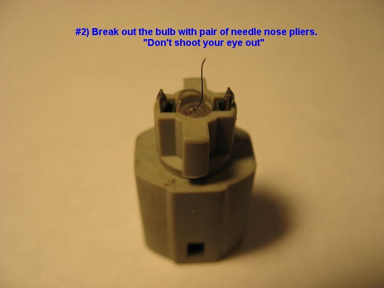
The ashtray / ignition ring lights are #74 based LEDs and can be purchased here:
They are listed as “74 Wedge Base LED bulb” and are $1.19 a pop. They simply lock into the stock mr2 light sockets.
To see what my work used to look like click here
Notes - 01/07/07
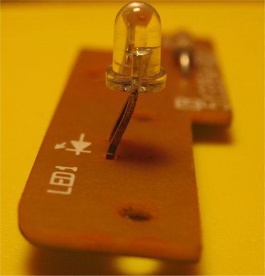
When soldering in new LEDs make sure you pay attention to polarity, The longer leg of the LED should always be soldered into/onto to positive hole/pad as indicated in my diagrams below.
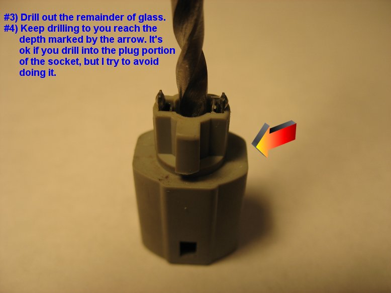
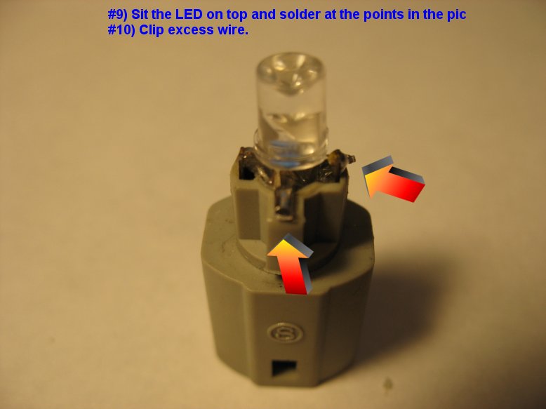
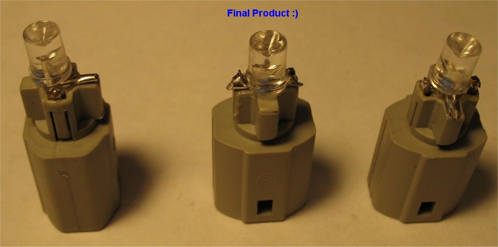
Cigarette Lighter Socket Modification
Notes - 01/07/07
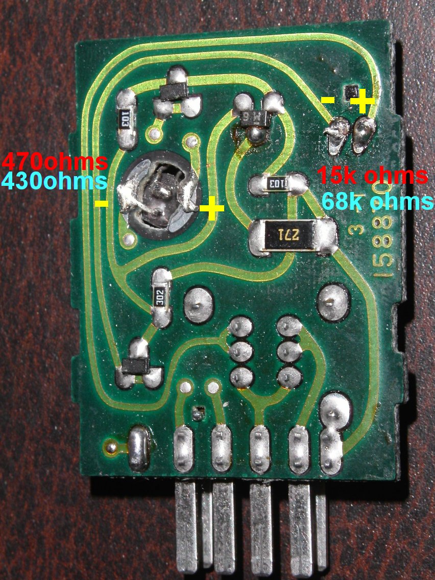
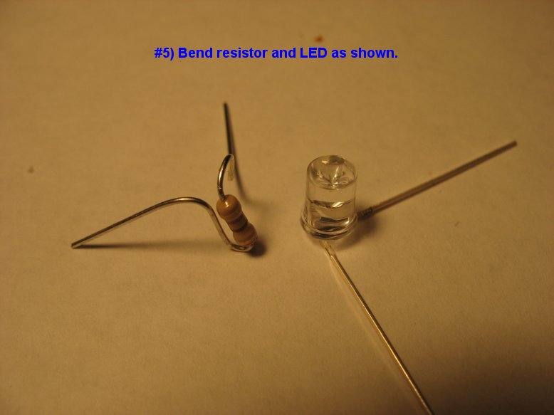
Use a 470 ohm resistor if modding with a red 360 degree LED
Use a 430 ohm resistor if modding with a blue 360 degree LED
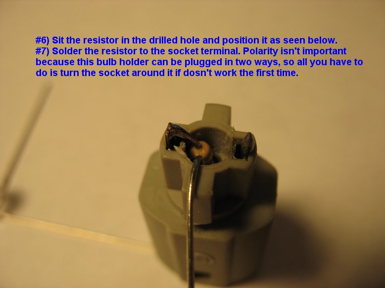
Polarity isn't important in this modification because the cigarette lighter socket is reversible. In other words, if the modified socket doesn't come on when you plug it in, turn it around and it will...
Drivers Side Door Control Modification
Notes - 01/07/07
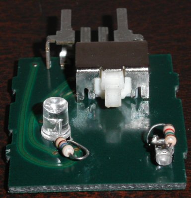
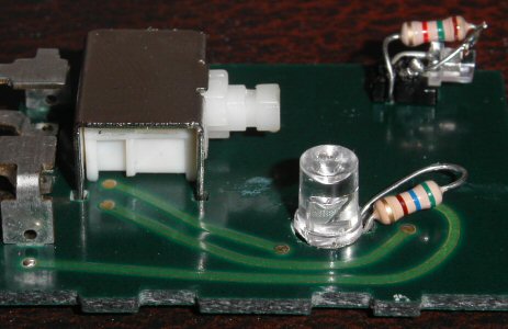
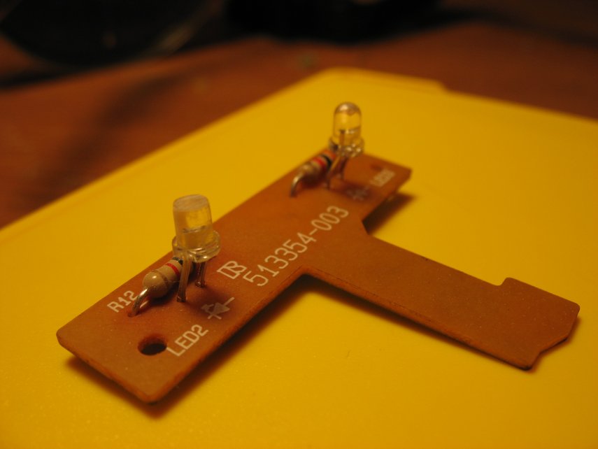
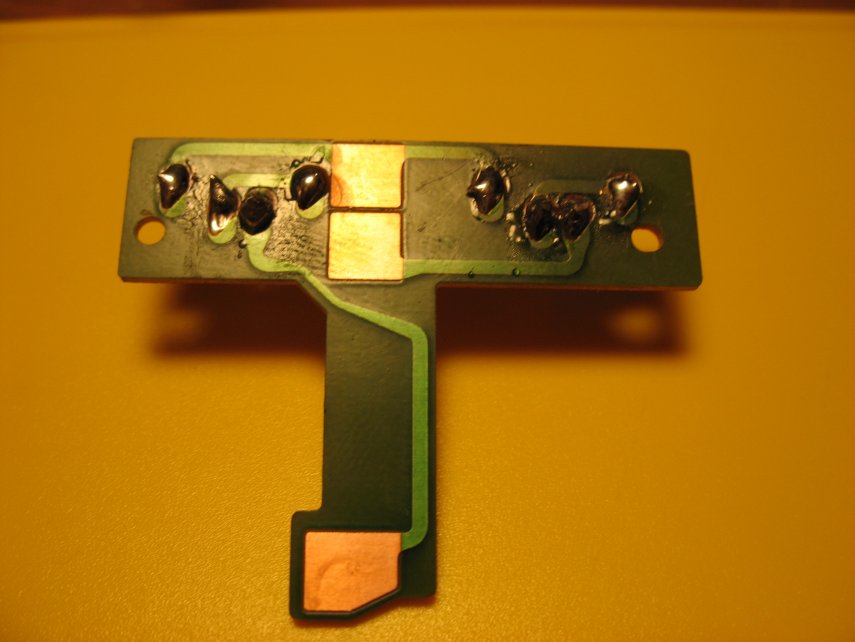
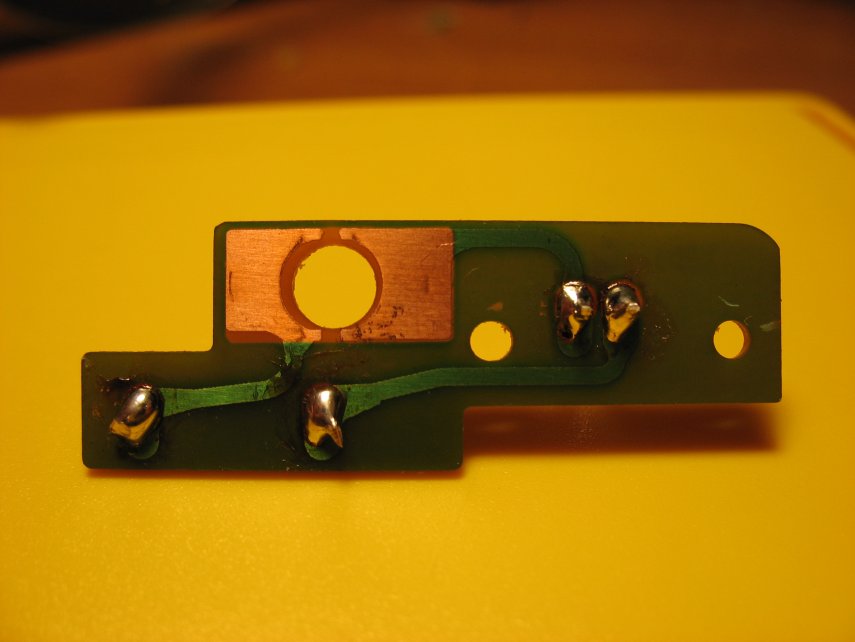
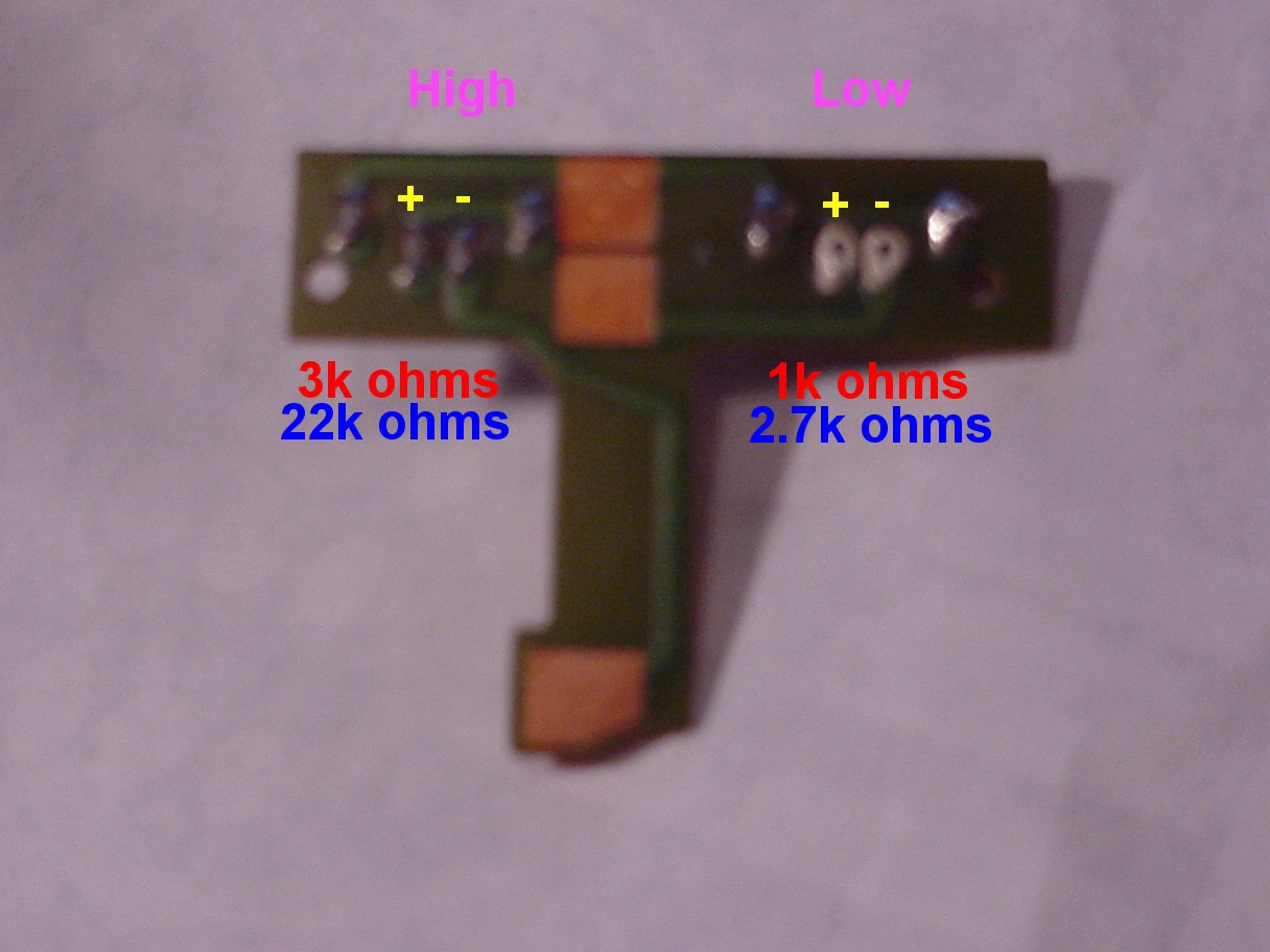
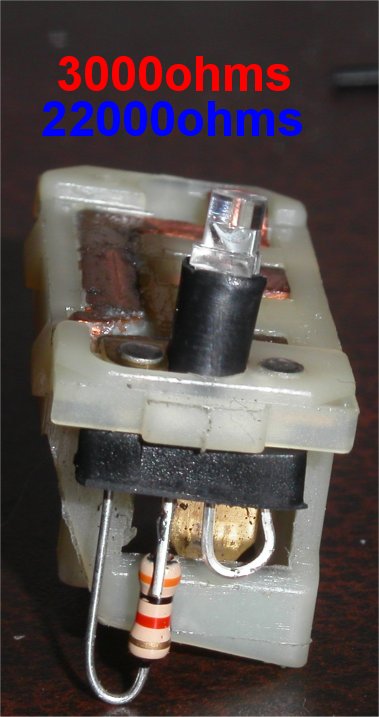
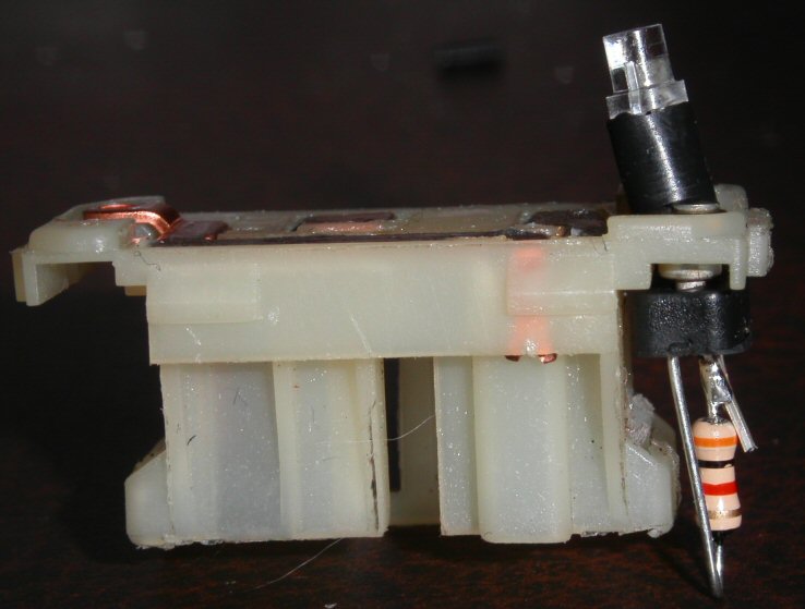
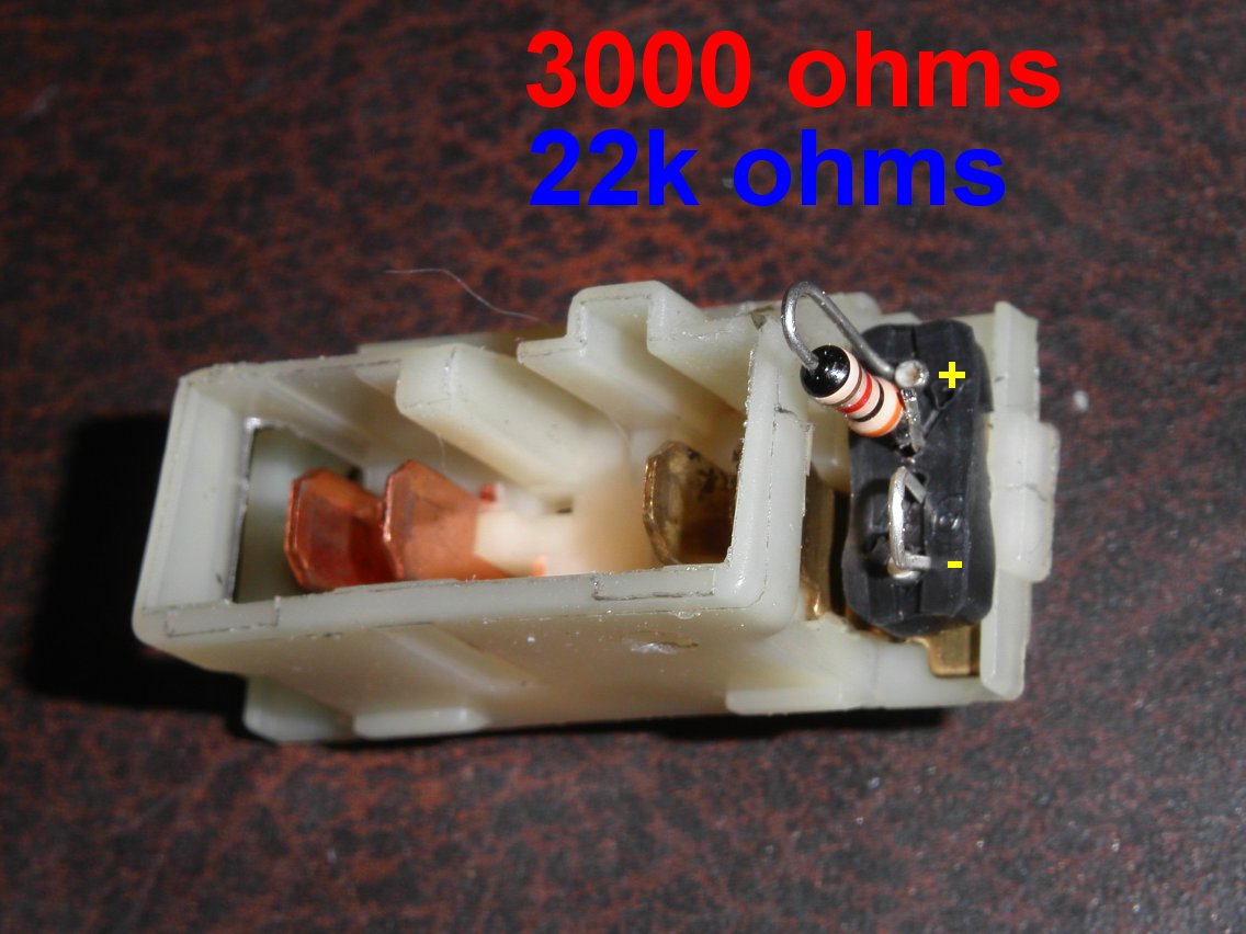
The pictures below show the two circuit boards that fit into the drivers side door control. The pictures show the resistance values needed to replace the stock leds with new blue or red leds, but more importantly, they show how the leds should be angled to fit correctly during reinstallation.
The picture directly below shows the circuit board & LEDs used to illuminate window switches. The one on the left needs to have the top sanded flat in order to properly illuminate the "auto" text without hotspots.
For some odd reason, I never made a diagram for the circuit board that illuminates the door lock switch. I'm pretty sure it uses a 1k ohm resistor for red or a 2.7k ohm resistor if your doing blue, however, if that turns out to be too bright, then use a 3k ohm for red or a 22k ohm resistor for blue.
Foglight Switch Modification
Climate Control Modification
Notes - 01/07/07
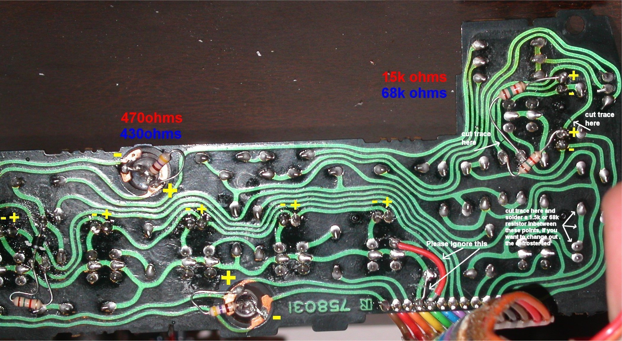
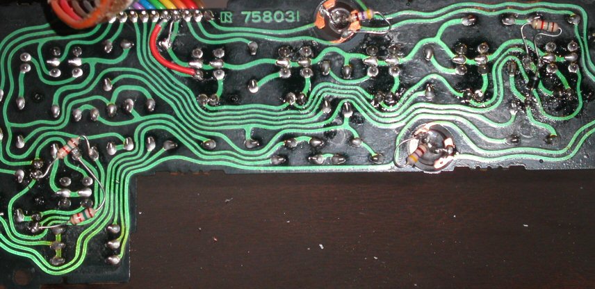
In the picture below there are three resistors with brown, green, red, and gold color bands. These resistors regulate the current going to the indicator LEDs and have a direct effect on their brightness.
The resistor on the left of the picture controls the current to the indicator lights that light up the 5 main buttons across the front of the CC. In the picture you can clearly see it is soldered in series with something else. This something else is a diode. The was originally soldered on the other side of the board and it originally connected to top point it is currently soldered to and the bottom point the resistor is currently soldered to. To do the mod like I did it, desolder the diode, pull it out and move it to the backside of the board. Next put the leg of the diode without the grey/white band into the top hole. After doing this, cut and bend the correct resistor (1.5k for red, 68k for blue) so that it will fit in the bottom hole and also touch the bottom leg of the diode. Finally, solder the resistor to the bottom hole, solder the resistor to the bottom leg of the diode, then solder the top leg of the diode to the top hole.
The two resistors on the right of the picture regulate the current to the 2 indicator lights that illuminate the airflow button on the CC. After desoldering the old indicator LEDs and soldering in two new ones, cut the green circuit traces with a razorblade where necessary (going over the trace 2-3 times with moderate pressure should easily do the trick). Lastly, solder in the two required resistors (1.5k for red, 68k for blue).
At the bottom right of the picture you'll see a note about the rear defroster LED. Usually when I did this mod in red, I left the stock amber rear defrost LED alone, because I liked the contrast between red and amber and it really let you know when your rear defrost was on. However, if you want to change this LED to red or blue, follow my notes in my picture.
The backlight LEDs are 360 degree LEDs ordered from Quickar. I usually scraped the copper contact pads with a razor blade to help promote solder adhesion before I got started. Also, it's not shown in the picture, but I would usually squirt a little hot glue in with the backlights to keep the assembly from moving around and shorting out.

Climate Control AC Button Modification